Hello Everyone
Its been a while again since my last post, but I’ve been a bit busy and preoccupied with various other things as well. Luckily I have some good news at least regarding the temperature measurement of the unit. I was working on the temperature calibration algorithm but got stuck. I seemed to have hit a mental block on how to proceed. I then re-evaluated whether the my initial calibration was working correct or not. I established that it wasn’t working correctly on initial testing. According to the datasheet of the AD597, the AD597 can only source an output up to 2V below the supplied voltage (Vcc). Vcc in my case is 5V so then according to the datasheet, my maximum output should only be 3V that I should be able to get from the AD597.
For this reason I have referenced my Aref pin on my Arduino to 3V. This means that 0 – 3 V will equal a RAW value of 0 – 1023 (Full range of 1024 values). The AD597 sources 10mV / °C which means that I should be able to measure up to 300 °C which is more than enough for the solder reflow process. So I determined that I can divide my digital RAW value by 3.142 ( 1024 / 300 = 3.413 ) to get the temperature measured (I call this variable my calibration factor). So when I tested the measurement in ice, it was working correctly. But in a boiling kettle it wasn’t measuring 100 °C but rather 70 °C. For this reason I determined that I had to implement the temperature calibration protocol.
After heating the thermocouple up with a fire source i.e. hot hot hot, I measured the output sourced by the AD597 with my multimeter and it was more than 3V. It was actually round about 4V. So this meant that my Aref voltage was incorrect. I then removed the voltage divider to reference Aref to 3V and left it and set Aref internally back to 5V. Since there is only 1V difference the resolution loss shouldn’t be too significant. Since the datasheet specifies that the AD597 sources 10 mV / °C, this meant that I would theoretically by able to measure a maximum temperature of 500 °C (Since RAW value 1023 = 5V). This also meant that I would have to change my calibration factor to work with the new theoretical maximum temperature. So the new value should be 1024 / 500 = 2.048. I then tested my temperature measurement and is seemed to be spot on compared to my Samsung S4 temperature sensor when measuring room temperature.
I then went ahead and retested the ice and boiling kettle temperature. Sure enough, in the kettle it was measuring around 100 °C but the value was fluctuating rapidly and quite a bit ( 80 °C – 115 °C) . So I then implemented an averaging function to get a more constant reading. This worked but the reading was still fluctuating quite a bit. I then reasoned that since the thermocouple has such a fast response time, that when a air bubble in the kettle hits the thermocouple, the air inside the bubble won’t necessarily by at 100 °C. So I determined that this was likely not a very good way to test the measurement.
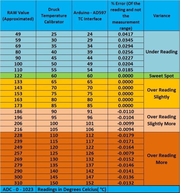
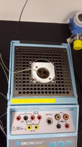
Luckily I am a instrumentation technician so I have access to some useful tools for this project. I used the company’s temperature calibrator to test how my measurement compared to a referenced calibrated measurement. The only draw back is that the calibrator could only go up to a maximum temperature of 150 °C and not 260 °C or 300 °C. Still this gave me a very good insight of how my measurement was performing. Below you will see the results.
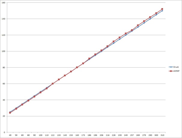
As can be seen from the results, the temperature is very close to the actual temperature. It should just be noted that the AD597 temperature variable is stored into an integer variable, meaning, should the temperature reading be 1.00 °C , 1.24 °C, 1.57 °C , 1.67 °C, 1.88 °C or even 1.99 °C, the reading will be rounded down to the nearest integer. Meaning with all the measurements in my example, the displayed temperature reading would be 1 °C. So armed with this information I have identified some measuring bands where my temperature reading were either over or under reading. But an uncertainty of 3 °C / 4 °C (Estimated at about 260 °C) is enough for the reflow process to work fine. So I will still implement the calibration protocol at a later stage should the user wish to get highly accurate readings (This protocol will unfortunately not be able to work with the Arduino UNO since the program space is not enough. A user that would like to implement it will have to use an Arduino Mega). Below is the results in a graph with the temperature in °C as the Y-axis and the RAW value as the X-axis:
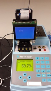
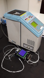
Below are some pictures of how I got these values:
My unit displaying the temperature compared to the calibrator reading.
The whole setup
Closeup of the heating pocket where temperature probes are inserted into so that the heat can be transferred to the temperature probes.
Hi there,
Interesting how minds think alike, also in the process of building a Arduino controlled reflow-oven based on a mini-oven. Very interested in the schematics and software if your willing.
Keep me posted
Remi
Hello Remi
Almost done with it. Planning on making everything open source once I’m done. Still need to resolve a few coding issues and then redesign the boards for easier mounting into an enclosure. But after that it should be happy days 😉
Dirk
Actually was still just looking for a oven and comparing prices vs specs. My goal is to build one under €100,- and thinking about a modulating or switched version when I saw your blog. The open source means you’re posting also the eagle files (or whatever program you are using?)
Remi
Hello Reni
I’m using eagle to design by boards so yes I will share these files too once done, open hardware as well as op en firmware.
Dirk
Great, got a cheap address where you can have pro PCB made on low volumes. 😉
Remi
[…] If Kickstarter isn’t your thing, [Dirk] created his own reflow controller. Like the Zallus, this has a graphical display, but its homebrew lineage means it should be simpler to maintain. It uses a K-type thermocouple, and unlike every other reflow controller we’ve ever seen, [Dirk] is actually checking the accuracy of his temperature probe. […]
I’m very late to this party….
> I then went ahead and retested the … boiling kettle temperature. … I then
> reasoned that since the thermocouple has such a fast response time, that when
> a air bubble in the kettle hits the thermocouple, the air inside the bubble
> won’t necessarily by at 100 °C.
Those are not bubbles of air, they are bubbles of steam. Assuming pressure is constant (atmosphere), and the steam is not dry (some liquid water is present in the vapor i.e. fog), then temperature can be determined using pressure.
A boiling pot of water at 70C? Hmm.. Could be firmware… or hardware. You eventually found it was hardware related, but a simple way to check for hardware issues would have been to capture the raw AD597/ADC values while the pot temperature was rising from ice to boiling. I’d expect steadily rising values (more or less) if everything was working. If the values plateau somewhere (say, about 614) well before reaching boiling, then a hardware mismatch would be clearly indicated.
Repeating a similar test with the existing reflow oven and an independent temperature measurement can check for similar performance. Depending on the quality of the measurement device and the speed of the warm-up, you could also extract calibration data for your sensor.