Hello everyone
I just had to put together a little guide to show how easy it would be to use the Reflow Master Shield with your toaster oven without having to hack your toaster oven apart. You’ll need to make up a extension cord cable which is connected to the relay which will effectively switch power through the cable.

So if you have your hacked extension cord (A), then you should plug in your toaster oven’s power connector into the socket side of your hacked extension cord. Then you will have to set your oven’s temperature to the maximum it can be set to (B). Lastly you’ll have to put your thermocouple into your grid section (It doesn’t have to be here but I think that this is the best placement to get the most accurate measurement of your temperature). I’ve just weaved it in there (C). Please make sure that the tip of the thermocouple doesn’t touch any metal parts of the oven or the grid as this will earth the thermocouple and then you’ll get bogus temperature readings.

So in short:
Hack a power extension cord and plug in the oven into the power extension cord.
Set the oven to the maximum temperature and if yours have switches that bypasses the temperature setting, switch it on
Insert the thermocouple into the oven.
If you don’t have a hacked power extension cord cable and don’t know how to make one up then you can follow the following guide. But before we start with it, just a little disclaimer:
Working with high voltage is DANGEROUS. Make sure that you know what your doing and that you have the proper knowledge before hand. Your use of any information on this guide is entirely at your own risk for which Paladin Enabling Technologies will not be held liable for. I do not take responsibility for your actions and you follow this guide completely at your own discretion.
Step one, get yourself a short extension cable from your local hardware store or Ebay etc.

This one from ebay – 1 ft / 300 mm
If you a socket that is removable, then follow the following steps:
I have my own cable which I made up:

The tools that you’ll require are as follows:

The tools on the left hand side are what you’ll need. The Reflow Master Shield can work with an standard relay without any additional circuitry (Although adding a blocking diode is recommended), an relay module (operating with an positive voltage trigger) or an solid state relay. The DIY relay on the left hand side, the relay module in the middle and the solid state relay on the right hand side.
The tools on the right hand side are not a must but it is a nice to have to make the work easier. If you have a socket on your lead that can be taken apart then you can follow the following procedure:
BEFORE YOU DO THAT, MAKE SURE THAT THE EXTENSION CORD IS NOT PLUGGED INTO A WALL SOCKET, EXTENSION CORD OR ANYTHING THAT WILL PROVIDE POWER TO IT.

Remove the screws from the socket and remove the internal socket connection module.

Remove the live wire from the socket connection module and insert another wire in it’s place. The wire colors might differ according to your country. See the wire color chart for the different countries from Wikipedia:
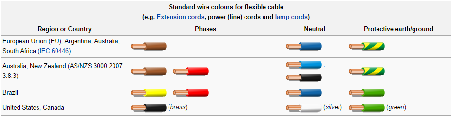
Live wire called the “phases” wire according to Wikipedia
Once you’ve inserted the “new” live wire, take both the “new” live wire and the “old” live wire back out of the socket connection module and housing. Now you can close the housing so that the “new” and the “old” live wires are outside the housing of the socket connection. So if you were to connect these now to a switch, plug in the extension cord into a wall socket and plug in another device. The device would power on if you switch on the switch.
We want to have this process happen automatically through the use of a relay. So we need to wire our relay into these wires. If you are using a solid state relay then you can connect each wire to a ~ connection of the solid state relay as seen below:

Then your good to go.
Alternatively, if you are using a DIY relay module or a bought relay module then you need to do the following:

Connect each wire to a terminal connection of a single relay. Make sure that there isn’t any copper wire visible from the terminal connections as this might cause a short circuit if the wires are moved into a certain position where the copper parts of the wires can touch. We don’t want this. If there are copper wire visible from the terminal connection then we need to cut the copper wire visible from the insulation a bit shorter and then insert it into the terminal connection again. When done, the insulation of the wire should be flush with terminal connection so that if the wire is moved in any way that the exposed copper parts of the wires can’t touch one another. Also make sure that you tighten your terminal connections tightly so that the wires are secure.
Now you will be able to use this cable but I would like you to take some extra steps before using it. If your going to be mounting it into a permanent installation into an junction box then the following steps can be skipped, if not, then you should follow the following steps:

The bottom copper of the board is exposed (The high voltage side encircled in red). If you were to plug in your hacked extension cord into a wall outlet and touch the bottom of the board in the red circled area then you would effectively earth the live voltage down to earth through your body and get electrocuted or shocked. So to prevent this from happening we need to insulate the high voltage side of the relay module. I recommend just using some insulation tape.
Start and tape the high voltage connection side closed and make sure that you go a few times around the module with the tape so as to have a few layers of tape so that the relay pins at the bottom won’t push through the tape and so making the tape insulation exercise null and void.
WORKING WITH MAINS VOLTAGE IS DANGEROUS SO DON’T SKIP THESE PROTECTIVE STEPS
If you’ve followed all of the steps and your unit looks like the above picture on the far right hand side then your good to go and you can use your hacked cable.
If you have a relay module then the exercise is pretty much the same as the previous one:

You’ll have some more options here. As seen in the far left picture above, there are three connections. The first is the normally open connection, the next is the common connection and the last is the normally closed connection. What does this mean you might ask, the common contact switches from your normally closed contact to your normally open contact once the relay coil is energized. If you wire the two wires to the common contact and the normally closed contact then the device connected to the socket will always be powered until you energize the relay coil at which stage the common contact will switch over from the normally closed contact to the normally open contact. At this stage the relay will power down your device that is connected to the socket until the relay coil is deenergized.
We don’t want to have the relay work like this. We want the relay to power “on” the device connected to the socket once we energize the relay coil. So we must connect our wires on the normally open contact and the common contact. Once again, if your not going to be mounting the relay module into an enclosure then you MUST insulate the high voltage side of the relay module. This is the section encircled in red. We insulate the high voltage section by using the insulation tape again. Please also check that your insulation of your wire is sitting flush with the terminal connection so as to avoid accidental short circuits between the “new” and the “old” live wires.
If you don’t have a socket that is removable, then follow the following steps:
If you’ve procured an extension cord as the Ebay example then you’ll need to cut the wires to be able to connect the relay. I recommend cutting along the side of the cable so that you only strip the outer insulation of the cable and not the inner cores’ insulation.

So once you’ve stripped away a bit of the insulation, pull out the inner cores of the wire to separate the inner cores from the insulation. Now you can cut the insulation so that it is split into two parts.

If this is done then you can clamp the one piece using your pliers. You can now pull away and the insulation should peal away as your pulling. Pull away enough insulation so that you have a decent length of the inner core wires exposed. Once this is done you can cut off the insulation that you’ve pealed off the inner cores.

If this is done you want to cut the live wire which in my country’s case is the brown wire. Please consult the Wikipedia extract to make sure which wire is the live wire in your country.
Once the wire is cut, you must strip the front bit of insulation of each cut wire so that you can use this to wire into your DIY relay module, bought relay module or your solid state relay.

If the live wire’s insulation have been removed and the copper is exposed, then you can start wiring your relay. I’m going to start off with the solid state relay. You need to connect each of the cut wires to the ~ connections (This symbol symbolizes alternating current) of the solid state relay. Once this is done, I recommend that you use your insulation tape to tape the cords together so that if you yank it somehow that it won’t pull out the live connection free from the solid state relay’s terminal connections (This is unlikely but an extra precaution). If you’ve done all of this then your hacked extension cord cable with relay is ready.
If your using a DIY relay then you’ll need to follow the following steps:

Connect each live wire to a terminal connection of one relay. Make sure that the insulation is sitting flush with the terminal connection so as to avoid any accidental short circuits. Also insure that you tighten the terminal connections thoroughly to avoid a wire from coming loose accidentally.
Also remember that the bottom copper section of the board is exposed and has electricity flowing through it (When connected to a wall socket) so if you were to touch it whilst the relay coil is energized then you would get electrocuted or shocked. To avoid this we need to cover the red circled area with insulation tape to make sure that it is safe. If your cord looks like the far right hand picture above then your good to go.
If your using a relay module that you’ve bought then you want to connect the wires to the normally open connection and the common connection. Please read further up where I have explained this if you don’t understand the difference between the three contacts.

If you’ve connected your wire and there is some copper visible from the terminal connection then you should cut the exposed copper of the wire shorter so that when it is mounted into the terminal connection that the insulation of the wire sits flush with the terminal connection.
Once again, the bottom pins of the relay carries the current and if you touch it whilst the relay coil is energized then you will be electrocuted or shocked. Please cover this part of the relay module (red circled area) with insulation tape to insure that you won’t accidentally be electrocuted or shocked.
If you’ve done all of this then your good to go to use this cord with the Reflow Master Shield. You can now reflow your boards as you wish 🙂
If you have any questions, feel free to drop me a comment. Wishing you all a wonderful day and weekend ahead.

[…] Kickstarter isn’t your thing, [Dirk] created his own reflow controller. Like the Zallus, this has a graphical display, but its homebrew lineage means it should be simpler […]
[…] Kickstarter isn’t your thing, [Dirk] created his own reflow controller. Like the Zallus, this has a graphical display, but its homebrew lineage means it should be simpler […]
[…] Kickstarter isn’t your thing, [Dirk] created his own reflow controller. Like the Zallus, this has a graphical display, but its homebrew lineage means it should be simpler […]
Hi
Pretty great project you got. Will you do a small store about this one too ?
Thanks
Hello Johny
Thanks for the kind comment. I’m not sure I follow you when you ask that I’ll do a small store about this one too?
Do you mean that I’ll make the board available for sale?